- 您现在的位置:买卖IC网 > Sheet目录314 > AUIRS2302S (International Rectifier)IC DRIVER HALF-BRIDGE 8SOIC
AUIRS2302S(TR)
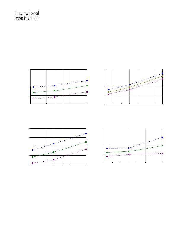
Parameter Temperature Trends
Figures illustrated in this chapter provide information on the experimental performance of the AUIRS2302S HVIC. The
line plotted in each figure is generated from actual lab data. A large number of individual samples were tested at three
temperatures (-40 oC, 25 oC, and 125 oC) in order to generate the experimental curve. The line consists of three data
points (one data point at each of the tested temperatures) that have been connected together to illustrate the
understood trend. The individual data points on the Typ. curve were determined by calculating the averaged
experimental value of the parameter (for a given temperature).
900
800
300
250
700
600
M ax.
Typ
200
150
M ax.
Typ .
M in.
M in.
500
100
-50
-25
0
25
50
75
100
125
-50
-25
0
25
50
75
100
125
140
110
Temperature ( o C)
Figure 7. Turn-On Time vs. Temperature
45
35
Temperature ( o C)
Figure 8. Turn-Off Time vs. Temperature
80
M ax.
25
M ax.
Typ.
50
Typ.
15
M in.
M in.
20
-50
-25
0
25
50
75
100
125
5
-50
-25
0
25
50
75
100
125
Temperature ( C)
Temperature ( o C)
Figure 9. Turn-On Rise Time vs. Temperature
www.irf.com
12
o
Figure 10. Turn-Off Fall Time vs. Temperature
? 2010 International Rectifier
发布紧急采购,3分钟左右您将得到回复。
相关PDF资料
AUIRS2336S
IC GATE DRIVER HV 3PHASE 28SOIC
AUIRS4426S
IC DRIVER LOW SIDE DUAL 8SOIC
AUIRS4427STR
IC DRIVER LOW SIDE DUAL 8NSOIC
AUIRS4428S
IC DRIVER LOW SIDE DUAL 8SOIC
AWH50G-0202-IDC-R
CONN PIN IDC 50POS W/O MT EAR
AWH50G-E232-IDC-R
CONN PIN IDC 50POS W/ FLANGE
AWP08-7541-T-R
CONN SOCKET IDC 10 POS W/KEY TIN
AWP14-7541-T-R
CONN SOCKET IDC 14POS W/STR TIN
相关代理商/技术参数
AUIRS2302STR
功能描述:功率驱动器IC AUTO HALF BRDG DRVR 600V 5V to 20V 60ns RoHS:否 制造商:Micrel 产品:MOSFET Gate Drivers 类型:Low Cost High or Low Side MOSFET Driver 上升时间: 下降时间: 电源电压-最大:30 V 电源电压-最小:2.75 V 电源电流: 最大功率耗散: 最大工作温度:+ 85 C 安装风格:SMD/SMT 封装 / 箱体:SOIC-8 封装:Tube
AUIRS2332J
功能描述:功率驱动器IC AUTO HI VTG HI SPEED 600V 3-Phase 540ns RoHS:否 制造商:Micrel 产品:MOSFET Gate Drivers 类型:Low Cost High or Low Side MOSFET Driver 上升时间: 下降时间: 电源电压-最大:30 V 电源电压-最小:2.75 V 电源电流: 最大功率耗散: 最大工作温度:+ 85 C 安装风格:SMD/SMT 封装 / 箱体:SOIC-8 封装:Tube
AUIRS2332JTR
功能描述:功率驱动器IC AUTO HI VTG HI SPEED 600V 3-Phase 540ns RoHS:否 制造商:Micrel 产品:MOSFET Gate Drivers 类型:Low Cost High or Low Side MOSFET Driver 上升时间: 下降时间: 电源电压-最大:30 V 电源电压-最小:2.75 V 电源电流: 最大功率耗散: 最大工作温度:+ 85 C 安装风格:SMD/SMT 封装 / 箱体:SOIC-8 封装:Tube
AUIRS2334S
功能描述:功率驱动器IC Automotive HiSpd Pwr MOSFET & IGBT Driver RoHS:否 制造商:Micrel 产品:MOSFET Gate Drivers 类型:Low Cost High or Low Side MOSFET Driver 上升时间: 下降时间: 电源电压-最大:30 V 电源电压-最小:2.75 V 电源电流: 最大功率耗散: 最大工作温度:+ 85 C 安装风格:SMD/SMT 封装 / 箱体:SOIC-8 封装:Tube
AUIRS2334STR
功能描述:功率驱动器IC Automotive HiSpd Pwr MOSFET & IGBT Driver
RoHS:否 制造商:Micrel 产品:MOSFET Gate Drivers 类型:Low Cost High or Low Side MOSFET Driver 上升时间: 下降时间: 电源电压-最大:30 V 电源电压-最小:2.75 V 电源电流: 最大功率耗散: 最大工作温度:+ 85 C 安装风格:SMD/SMT 封装 / 箱体:SOIC-8 封装:Tube
AUIRS2336S
功能描述:功率驱动器IC 3-Phase Bridge DRVR 600V 200mA 275ns RoHS:否 制造商:Micrel 产品:MOSFET Gate Drivers 类型:Low Cost High or Low Side MOSFET Driver 上升时间: 下降时间: 电源电压-最大:30 V 电源电压-最小:2.75 V 电源电流: 最大功率耗散: 最大工作温度:+ 85 C 安装风格:SMD/SMT 封装 / 箱体:SOIC-8 封装:Tube
AUIRS2336STR
功能描述:功率驱动器IC 3-Phase Bridge DRVR 600V 200mA 275ns RoHS:否 制造商:Micrel 产品:MOSFET Gate Drivers 类型:Low Cost High or Low Side MOSFET Driver 上升时间: 下降时间: 电源电压-最大:30 V 电源电压-最小:2.75 V 电源电流: 最大功率耗散: 最大工作温度:+ 85 C 安装风格:SMD/SMT 封装 / 箱体:SOIC-8 封装:Tube
AUIRS44261S
功能描述:功率驱动器IC Dual Low Side DRVR 25V 2.3A 70ns AUTO RoHS:否 制造商:Micrel 产品:MOSFET Gate Drivers 类型:Low Cost High or Low Side MOSFET Driver 上升时间: 下降时间: 电源电压-最大:30 V 电源电压-最小:2.75 V 电源电流: 最大功率耗散: 最大工作温度:+ 85 C 安装风格:SMD/SMT 封装 / 箱体:SOIC-8 封装:Tube
